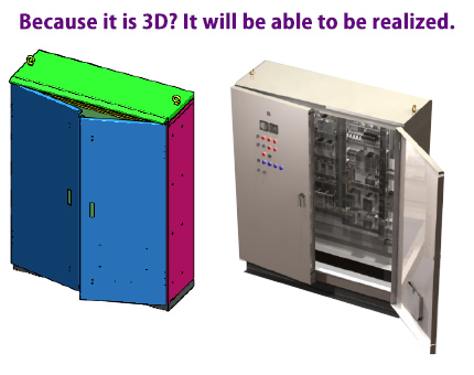
In recent years, designs that are difficult to make in reality due to design errors or inefficiencies from the background such as low cost and short delivery time, or designs that are difficult to produce accuracies are no longer acceptable situations.
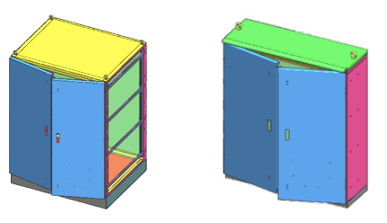
“Imitations” exist in many products. Similar products can be produced when the dimensions of products that are literally similar are slightly changed.
Sheet Works parametrically transform all models at any stage.
Implementation of board design with 3-dimensional CAD (introduction of SolidWorks-based mechanical system 3D / CAD "SheetWorks"
3D CAD Background

Things that can be done by making it three-dimensional
Until now … Design specification document → 2D drawing → development drawing
From now on … Design specification document → 3D modeling → 2D drawing (development drawing)

· Processing propriety judgment
· Processing balancing (production design)
· Interference check in assembly (static / dynamic)
· Analysis (CAE) Deformation analysis · Thermal analysis etc.
· Utilization of electronic drawings (e-drawings)
Assembly manual
VA / VE proposal
Features of 3D CAD (Difference from 2D CAD)
Drive size
Besides representing the size of the product, the size can drive the dimensions of the product to the specified size.
Dimension link
All linked dimensions are changed to the same size by changing only one dimension.
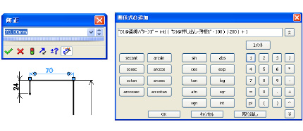
Relational expression
Design requirements such as hole pitch and numbers can be registered as a relational expression in the model.

What is Sheet Works parametric function?
The parametric function of Sheet Works is “an automatic design tool applying the function of three dimensional CAD”.
If you make a model, you can create expansion plan of different dimensions by simply entering variables such as WHD.
Anyone can create a development map without mistakes by incorporating the processing rules and know-how into the template.

Parametric operation
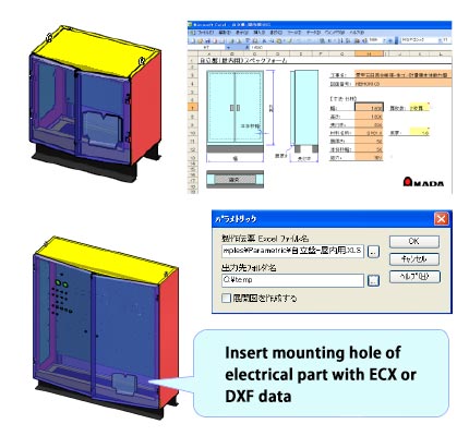
After preparing the station model and the input form, we then execute the parametric by entering variables according to the order.
After deformation, insert the special hole and additional parts of the product to complete the design.
Electric part mounting holes can be easily inserted, if there is mounting diagram information (ECX) or DXF data, which output from electric CAD such as ACAD, ECAD.

Summary
Benefits of designing with 3-dimensional CAD
· Three-dimensional data created by design can be used as it is, so it is possible to shorten the leading time of designing to manufacturing and reduce mistakes.
· It becomes easier to make the image in design review, and requests from other sections can be corrected and reflected early.
· It can be used for manufacturing manuals and various documents.
Sheet Works can significantly innovate sheet metal operations
· Design · Burdens of production design work
Three-dimensional modeling can be done in a way that will not be burdens of the designer, such as enclosures, fasteners, etc. The manufacturing side can easily replace them with processing information.
· Steel material processing
Not only sheet metal work but also the design and manufacturing of steel materials becomes dramatically more efficient.
